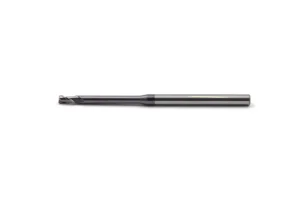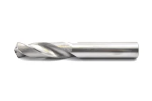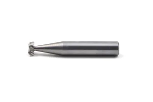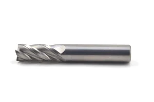
Explore our primary collection of industrial-grade milling tools engineered for long tool life and exceptional surface finish quality.
We are a professional, state-of-the-art manufacturer of cutting tools, specializing in the design, development, and production of high precision carbide tools. Our comprehensive production lineup includes premium quality milling cutters, carbide drills, reamers, and boring cutters. Our structural engineering advantages lie in our specialized micro endmills and high-performance carbide drills.
To guarantee unmatched precision and quality assurance, our manufacturing facility relies on world-class grinding machinery including German "Walter" systems, Swiss "TTB" systems, and "Joerg" tool grinders. Every single tool batch undergoes rigid metrology inspection utilizing industry-standard "Zoller" measuring devices to verify profile accuracy, helix deviations, and surface finish metrics before global delivery.
Explore our standardized product series designed for precise geometries and complex manufacturing profiles.
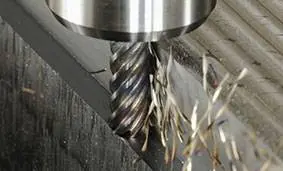
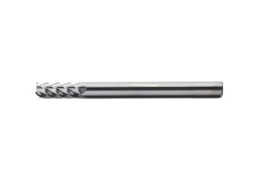
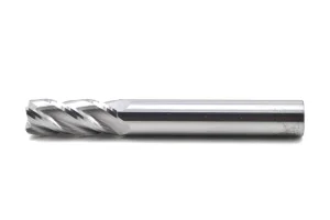
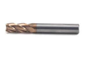
(square end mill) MCXD-S
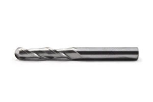
(ball nose end mill) MCXD-BN
(corner radius end mill) MCXD-CR
(Aluminum end mill) MCXD-A
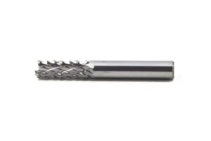
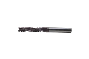
(Roughing end mill) MCXD-R

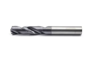
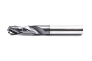
(Twist drill bit) MCZT-T
(Drill bit with Inner coolant) MCZT-IC
(Step drill bit) MCZT-S
(center drill bit) MCZT-C
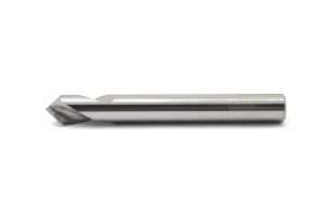
(Nc spotting drill bit) MCZT-N
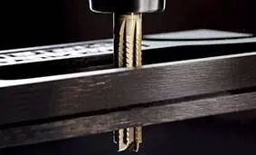
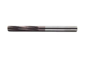
(straight flute reamer) MCJD-ST
(spiral flute reamer) MCJD-SP
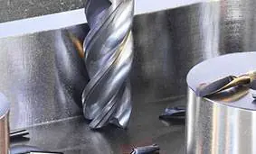
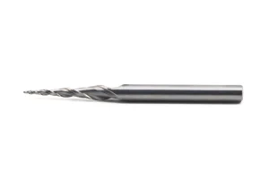
(CNC Engraving Tools) MCDZ-E
(T-slot end mill) MCDZ-T
(customized milling cutter) MCDZ
A deep technical dive into carbide ball nose milling technology and substrate development.
The evolution of solid carbide ball nose milling cutters is deeply rooted in grain boundary engineering. At Millcraft, we leverage nano-grain and ultra-fine sub-micron tungsten carbide (WC) substrates with a cobalt binder content optimized between 8% and 12%. This delicate balance guarantees superior fracture toughness while keeping critical edge hardness intact, allowing tools to perform at temperatures exceeding 1000°C.
Traditional chemical coatings fall short under high dynamic stress. Our upcoming technological roadmap highlights HiPIMS (High-Power Impulse Magnetron Sputtering) coatings, specifically TiAlN, nACo, and diamond-like carbon (DLC) structures. These coatings introduce a compression stress barrier that inhibits micro-crack propagation, significantly extending tool service life in high-speed dry machining environments.
To eliminate dynamic resonance (chatter) during high-speed feed rates, we design ball nose mills with variable helix angles (varying between 35° and 40°) and asymmetrical pitch layouts. This design disrupts harmonic frequencies, ensuring uniform chips and reduced surface roughness (Ra) down to sub-micron levels on complex 3D mold profiles.
Adapting ball nose geometries to demanding industrial requirements and materials.
Aerospace turbine blades and impellers are composed of hard-to-cut nickel-based superalloys (such as Inconel 718) and titanium (Ti-6Al-4V). Standard cutting profiles fail rapidly due to excessive friction and heat. Our aerospace-grade ball nose cutters integrate custom radius profiles and specialized heat-resistant barrier coatings that minimize tool wear at contact points, maintaining a clean cut under variable pressure.
Review Aero Specs →Automotive stamping dies require milling on pre-hardened tooling steels exceeding 60 HRC. Utilizing specialized ball nose profiles with structural core reinforcement enables high-speed finishing operations with zero edge chipping. This ensures surface continuity across large dies and eliminates secondary polishing operations, saving automotive manufacturers time and money.
Review Die Mold Specs →Manufacturing orthopedic implants and joint replacements requires machining biocompatible metals like Cobalt-Chromium (CoCr) and medical titanium. Our micro-fluted carbide ball nose end mills offer sharp cutting edges and optimized chip evacuating channels to prevent material work hardening and heat generation, resulting in smooth finishes that meet strict medical quality guidelines.
Review Medical Implant Specs →Why Millcraft’s localized ecosystem delivers premium tooling at scale without compromise.
At Millcraft, we implement an automated "Smart Factory" blueprint that optimizes tool geometry production. By running lights-out automated cycles on our German Walter CNC grinding centers, we eliminate human errors and verify consistency across large batch orders. In addition, our close integration with premium tungsten raw material suppliers in China keeps our manufacturing secure from global price fluctuations.
By maintaining our own internal grinding wheel calibration systems and using high-precision Zoller inspection machines, we ensure that every batch of custom ball nose cutters matches specifications, minimizing set-up times and tooling variations for our global customers.
We operate close to the industrial logistics hub of Changzhou, ensuring swift, direct shipments to international ports and airports. We maintain stable inventories of raw material blanks, allowing us to respond quickly to custom tool requests and high-volume orders.
Key technical parameters required by procurement specialists and manufacturing engineers.
For precision mold-making, shank-to-cutting-edge TIR must be kept within 0.005mm. Minimizing runout prevents uneven flute wear, reduces early tool failure, and avoids surface scallops on finished parts.
All tool shanks are manufactured strictly in compliance with DIN 6535 Form HA (plain round shanks) and HB (Weldon flats). This compatibility ensures secure clamping in hydraulic, shrink-fit, and high-precision collet chucks.
The ball nose radius contour is checked on multi-axis optical inspection systems. Our standard tolerance of ±0.005mm (and up to ±0.002mm for premium series) ensures dimensional consistency on 3D contoured surfaces.
Meeting international standards, regulatory rules, and engineering requirements.
Our entire design and manufacturing workflow complies with ISO 9001:2015 quality management standards. Each production batch is assigned a unique batch number, providing full traceability back to the raw carbide powder batch, raw hardness levels, and coating cycle details.
Millcraft Tools ensures that all metallurgical formulations and physical vapor deposition (PVD) coating processes are completely free of hazardous materials, meeting European REACH and RoHS standards for environmental sustainability and safety.
Direct answers from our engineering team to solve your complex milling challenges.
The effective cutting diameter of a ball nose cutter varies based on the axial depth of cut (Ap). It is calculated using the formula: De = 2 * √(Ap * (D - Ap)), where D is the nominal cutter diameter. When performing shallow 3D profile milling, the actual cutting speed at the contact point is lower than the calculated speed based on nominal diameter. Therefore, spindle speed must be calculated using the effective diameter (De) rather than the nominal diameter (D) to maintain target surface speed (Vc).
Wear at the tip occurs because the cutting speed (Vc) drops to zero at the absolute center point of the ball nose. Without speed, the tool shears rather than cuts the material, leading to built-up edge and chipping. To prevent this, tilt the tool spindle (or the workpiece on a 5-axis machine) by 10° to 15°. This shifts the contact point away from the zero-speed center, improving chip formation and tool life.
For titanium alloys, we recommend physical vapor deposition (PVD) coated tools with AlTiN or TiAlN, or advanced silicon-doped nanocomposite coatings (nACo). Titanium has a high chemical affinity for cobalt, which can lead to rapid tool wear. These coatings act as a thermal and chemical barrier, preventing cobalt diffusion and protecting the carbide substrate under high heat.
Higher helix angles (above 40°) pull chips out of deep cavities quickly, reducing chip recutting. However, they also increase tensile forces on the tool. Using a variable helix design (e.g., 38° to 42°) balances force distribution and breaks up structural harmonics, helping eject chips smoothly from deep pockets without causing tool deflection.
To achieve smooth finishes (Ra < 0.4 μm), the stepover (Ae) should be calculated based on the allowable scallop height (h). The formula is: Ae = 2 * √(2 * R * h - h²), where R is the ball nose radius. Typically, the stepover should be kept between 5% and 10% of the cutter’s nominal diameter, paired with high spindle speeds and fine feed rates.
Stay updated with research findings, industry reports, and tool holder updates.
The End Mill Holders Market research report presents an exhaustive study of this business space, detailing key industry drivers, market share fluctuations, and the latest trends within the tool holding sector. The research highlights the critical importance of tool runout minimization, and the role high-precision collet and shrink-fit systems play in extending carbide tool life.
Introducing the Fullcut Mill Contact Grip. With the addition of the Fullcut Radius Mill (FRM) and the Ball End Mill (BE) geometries, the series now features four connection sizes and seven distinct cutter styles. The contact grip is a threaded coupling system that achieves high rigidity and torque transfer, matching solid tool performance in high-speed, multi-axis machining applications.
Discover our custom carbide drills, spotting bits, and flat end mills configured for specialized manufacturing setups.
Reach out for custom tooling inquiries, material compatibility testing, or to discuss production runs for your specific milling requirements.

Provide us with your drawings and workpiece material specs, and our design team will recommend optimal tool geometries.
Subscribe to Updates